IRON NEST Tactical Map Guide: Range, Bearing and Triangulation
How to turn coordinates, observer bearings and ranges into a target marker, then measure the turret-relative bearing and distance needed for a firing solution.
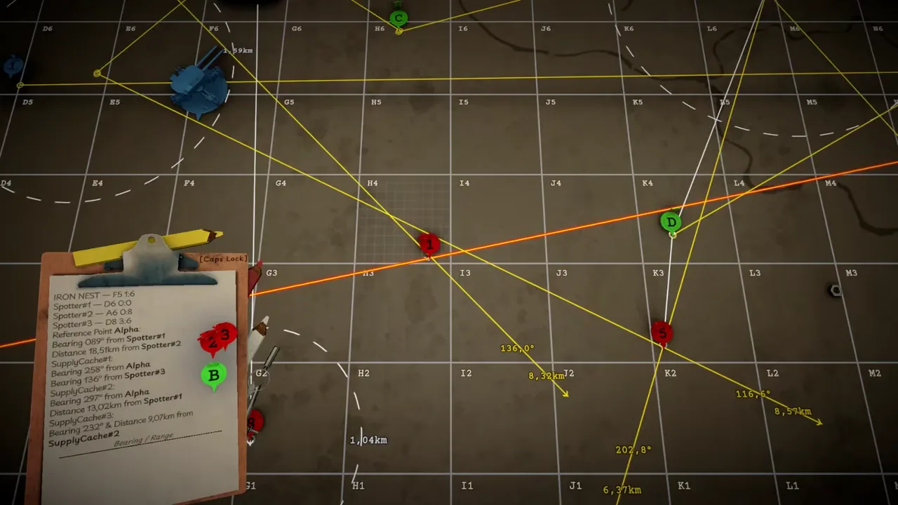
Every firing solution in IRON NEST: Heavy Turret Simulator begins with a location. The tactical map is where reports become that location and where the operator turns it into the two gun-facing values that matter next: bearing and range. A correct calculator cannot rescue a target plotted from the wrong observer or a distance measured from the wrong origin.
The official Steam description calls the map both a measurement tool and a window onto the battlefield. It receives coordinates and intelligence, holds markers and lines, and can be paired with aerial photographs that reveal consequences. The official demo footage above shows a labeled grid, observer markers, colored bearing lines and numeric distance annotations in active use.
This guide explains the reasoning supported by those sources. Interface details can change with patches, so exact clicks or key bindings should be learned from the current version 1.0 controls rather than assumed from a video frame.
Two map problems, not one
The operator often solves two related problems:
- Reconnaissance problem: Where is the target, given coordinates, observer positions, bearings, ranges or photographs?
- Firing problem: From the turret’s current position, what bearing and range lead to that target?
Keeping those stages separate prevents the most common conceptual error. A report that says a target is 10 kilometers from Spotter 2 does not necessarily mean the turret should enter 10 kilometers into its ballistic calculator. First use that distance to locate the target relative to Spotter 2. Then measure from IRON NEST to the resulting point.
Start by preserving the source report
Before drawing anything, identify the objective and copy its target label. Keep the original report visible so each line can be checked against it. When several spotters or supply locations appear on one clipboard, a bare number quickly loses its meaning.
Annotate values with their origin: “086° from Spotter 1” or “10.89 km from Spotter 2.” Direction and distance are relationships, not properties of the target alone. The origin is part of the data.
If the mission supplies a direct coordinate, verify both the main grid location and any finer subdivision shown by the current interface. Official footage confirms a letter-and-number grid with smaller divisions, but this page does not declare an unchanging total grid size for every region or mode.
Bearing answers “which direction?”
A bearing is an angle measured from a reference direction. On the tactical map, a reported observer bearing defines a line extending from that observer. The target lies somewhere along it, subject to any uncertainty in the report.
Plot the line from the named observer, not from the center of the map and not from the turret unless the report says the turret is the origin. Confirm orientation before accepting the line; reversing a direction by 180 degrees can create a clean, confidently wrong solution.
Colored lines are useful when several reports overlap. The official footage shows multiple colors and labels, making it possible to trace each geometric relationship back to its source.
Range answers “how far from here?”
A reported range defines distance from a specific origin. Geometrically, every point at that distance lies on a circle around the origin. The map’s measuring tools can represent that relationship as an arc or distance constraint.
When combined with a bearing line, the range can identify one or more intersections. When combined with another range, two circles may intersect. Mission context and additional intelligence determine which point is meaningful.
Do not replace an exact given range with visual estimation. Likewise, do not assume the straight-line distance printed near one colored line belongs to a different marker simply because it is nearby.
Locating a target with two bearings
If two observers report directions to the same target, plot each independently:
- Mark or verify Observer A’s position.
- Extend A’s reported bearing from A.
- Mark or verify Observer B’s position.
- Extend B’s reported bearing from B.
- Inspect their intersection and compare it with the mission context.
The intersection is the target estimate when the reports are treated as exact. In the May Q&A, the developer also discussed observation error and the idea of a probable target zone. If bearings have uncertainty, the useful answer may be an overlapping area rather than a mathematically perfect point.
Do not force non-intersecting lines together before checking transcription, origin and direction. Uncertainty is a later explanation, not a substitute for plotting the given data correctly.
Combining a bearing and a distance
One report may give a direction from Observer A while another gives distance from Observer B. Plot A’s line, then apply B’s distance constraint around B. Their intersection supplies a candidate target.
Some configurations produce two intersections. Use additional reports, terrain, objective description or photographs to choose between them. If no official clue distinguishes the candidates, the evidence is incomplete; guessing should be labeled as such rather than documented as confirmed coordinates.
This mixed method is still triangulation in ordinary gameplay discussion, although the geometry is technically a line-and-circle intersection rather than two bearing lines.
From target marker to firing bearing
Once the target is established, begin the second problem. Draw or measure from the IRON NEST marker to the target marker. The direction of that relationship is the turret bearing.
Official footage shows map lines annotated with degree values. Transfer the final turret-relative bearing to the traverse system, keeping the target label attached. A spotter bearing should not be copied directly to the gun unless the spotter and turret share the same position—which should never be assumed.
If the turret moves, this bearing becomes stale. The target may be unchanged while the origin has changed, so measure again.
From target marker to firing range
The same turret-to-target relationship supplies range. Official footage displays distance labels along plotted lines, while the calculator interface accepts target distance as an input.
Write the firing range beside the firing bearing: “Target D — 136.0° — 8.32 km,” for example. The values in that example are visible in a particular developer video frame and are not instructions for a current mission.
Take this range to the ballistic calculator, choose the intended powder charge and obtain elevation. Preserve the target label through the transfer so a later report does not combine new bearing with old range.
Using aerial photographs as evidence
The official Steam page says aerial photographs reveal outcomes and that the map is a window onto the battlefield. A photograph can confirm damage, expose a mistaken location or add context to a later objective.
Treat it as evidence with a time and subject. A new photograph should not be placed over an old target merely because the terrain looks similar. Compare grid features, labels and the report that delivered it.
Photographs can show that a technically correct impact produced an unexpected consequence. They do not automatically reveal which calculation step was wrong; that still requires tracing the solution.
Diagnosing map errors after a miss
If an impact is at about the intended distance but laterally displaced, inspect target plotting, firing bearing and traverse transfer. If it follows the correct direction but is short or long, verify firing range before blaming the calculator. If both axes are wrong, revisit the target’s original location.
These are clues, not perfect proofs. Perspective and uncertain observation can distort the apparent pattern. Preserve the plotted lines and gun settings until the evidence is understood.
Correct the earliest wrong step. Moving the target marker means bearing and range must both be measured again. Correcting only a copied bearing can preserve a valid range. Randomly adjusting the gun throws away the map’s diagnostic value.
Habits that keep a crowded map readable
Use one color per observer or evidence source. Label every line with origin, report and target. Cross out or remove obsolete solutions when the turret moves or an objective changes. Keep photographs associated with the event that produced them.
Before leaving the map, perform a short readback:
- Correct objective and target label.
- Every reconnaissance value plotted from its named origin.
- Target chosen from the supported intersection or coordinate.
- Final bearing measured from the turret.
- Final range measured from the turret.
- Both values recorded together for the next stations.
This organization matters because the map is a shared workspace for several stages, not a disposable puzzle screen.
Where the map fits in the complete firing loop
The teleprinters and reports tell the operator what information exists. The map turns that information into a target and turret-relative geometry. The ballistic calculator turns range and charge into elevation. The loading and gun-laying stations make the physical weapon match the solution.
Every downstream stage inherits the map’s accuracy. That is why careful plotting is not time wasted, even in a challenge. A clean target marker prevents repeated calculator work, unnecessary rotation and unexplained misses.
The tactical map rewards a simple discipline: preserve origins. Bearings come from somewhere, ranges are measured from somewhere and every solution becomes invalid when its origin changes. Keep those relationships visible, and the battlefield’s messy intelligence becomes a firing problem the rest of IRON NEST can actually solve.
Frequently asked questions
How do you locate a target from two bearings?
Plot each reported bearing from its own observer position. The intersection identifies the target or the center of a small probable area if the reports include uncertainty.
Which range goes into the ballistic calculator?
Use the distance from the IRON NEST's current position to the plotted target. An observer-to-target range helps locate the target but is not automatically the gun's firing range.
What is the difference between bearing and range?
Bearing describes direction from an origin; range describes distance from an origin. The turret needs both measured from its current position before the solution can be transferred to traverse and elevation controls.